Search Results
Search this site
1084 results found with an empty search
- Active Mold Packaging – Additive IC Packaging For mmWave Applications
Speaker: Florian Roick | Company: LPKF | Date: 10-11 March 2021 | Full Presentation This presentation investigates the capabilities of Active Mold Packaging towards mmWave application. First the dielectric properties of three different AMP-EMCs are measured in the D-band. Second, the reflection coefficient S11, as well as the H- and E-plane radiation patterns are determined for a set of AMP manufactured 60 GHz bow-tie slot and dual dipole antennas. Where the measured results are compared to the design values and differences are discussed. And third, the D-band EMI shielding effectiveness of the electroless plated Cu/Ni/Au layer on the surface of three different AMP-EMCs is measured. Florian Roick Business Development Manager Active Mold Packaging @ LPKF Bio M. Sc. Florian Roick, Business Development Manager Active Mold Packaging. Born in 1981. He holds a degree as Bachelor of Science in Applied Physics from Dublin Institute of Technology. And a degree as Master of Science in Electrical Engineering with focus on laser systems, laser physics and microsystems engineering from Hochschule Bremen. Since 2006 employed at LPKF Laser & Electronics AG, until 2008 as application engineer for the StencilLaser business unit. Between 2008 and 2019 strategic product manager responsible for aligning the product portfolio with the needs and requirements of the PCB and SMT markets. Since 2019 Business Development Manager for LPKF’s Active Mold Packaging technology. That is to electrically functionalize the real-estate of the epoxy mold compound on the base of LPKF’s patented Laser Direct Structuring (LDS) technology. Co-inventor of the parametric stick-in and co-author of a variety of publications. Join TechBlick on an annual pass to join all live online conference or online version of onsite conference access library of on-demand talks (600 talks + PDFs) portfolio of expert led masterclass year-round platform https://www.techblick.com/ And do NOT miss our flagship event in Berlin on 17-18 OCT 2023 focused on Reshaping the Future of Electronics. This event attracts 550-600 participants from all the world and offers a superb ambience and dynamic exhibition floor. To learn more visit https://www.techblick.com/electronicsreshaped To see feedback about previous event see https://www.techblick.com/events-agenda
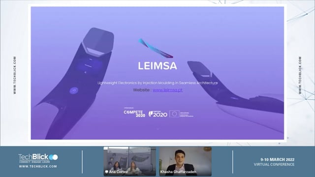
- LEIMSA – Lightweight Electronics by Injection Moulding in Seamless Architecture
LEIMSA is an ambitious 5M Euro project bringing together many of the key players across the value chain to create structural electronics using the integration of IMD (in-mold decoration), IML (in-mold labling), IME (in-mold electronics), HPF (high pressure forming, etc). The project partners include Simoldes Plastics Celoplás, Plásticos para a Indústria, S.A. DTx - Digital Transformation CoLAB Bosch. The project partners include Elantas Proell Covestro DuPont Hofmann Biebling Covestro Sabic Kurz Grewus, etc The final demonstrator will seemlessly integrate into a 3D console a transparent display, a capacitive display, a slider (capacitive | backlighted), touch buttons with RGB LEDS and haptic feedback, small display etc. In the video below Sandra Melo and Ana Cortez explain the parts that are being integrated using into the console
- What is the future market for microLEDs in terms of unit sales, application, chip type, backplane?
The slides below share some key forecasts and analysits by Jerry Kang from Omdia - one of the leading analysts in the field - who will present live online at TechBlick's microLED and QD event on 30Nov-1Dec www.TechBlick.com/microLEDs Slide 1 shows that the microLED market will experience substantial growth in the coming years. In 2021, the sales were expected to be just 0.12k units, reflecting the lack of technology maturity and the manufacturing high cost/low yield. In 2029, the figure is expected to reach 12.7M units per area. This is a transformational growth, and yet still represents just 0.3% of the total FPD market! Slide 1 also shows the split of the market - in thousands of units - by application. The first to arrive were public displays owing to low technical barriers and much larger dies as well as ultra low PPI. Premium TV have also arrived and will grow. Here, the superior performance of color gamut, luminance, and contrast delivers value. Smart watches will be a drive of unit sales, as here the small size and lower PPI translate to lower technical barriers. Slide 2 shows the evolution of the market by backplane technology. MicroLED on Silicon (on CMOS) is suited to high PPI AR or HUD devices. LTPS backplane is ideal for small and medium sized applications like smart watches due to high mobility of LTPS but LTPS does not scale to large areas due to non-uniformity of p-Si. Oxide TFTs can be scaled to Gen8 whilst PCBs will be used for ultra large displays such as signage. Slide 2 also shows the the forecast split by chip type. The on-wafer option means growing the uLED array directly on the epiwafer. Here, pixel can be very small but overall size limited by wafer size (6-12inch). Flip chip means that microLEDs will have bottom electrodes so that they can be flip chip mounted onto the target substrate/backplane Join us on 30Nov-1 Dec 2022 to learn more about the technology and market for microLED and Qunatum dots. You will hear from a fantastic lineup of speakers including Samsung, AUO, Sharp, ST Micro, Omdia, Yole, Coherent, Allos, etc. Check out the agenda here www.TechBlick.com/microLEDs Data in the slides from Omdia who will present in the event
- Technical & Styling Approaches For Intelligent Surface Illumination
Speaker: Mathias Rönnfeldt | Company: Lightworks | Date: 10-11 March 2021 | Full Presentation Current light system development is much more than the sum of the right light source, the material setup and light output. Together with our customers Lightworks GmbH is creating more and more user-oriented lighting experiences. Main focus is the seamless combination of innovative lighting technologies like IMSE as well as advanced surfaces, materials and processes out of our network. This approach allows maximum design freedom during concept and series development for our customers and their clients. Join TechBlick on an annual pass to join all live online conference or online version of onsite conference access library of on-demand talks (600 talks + PDFs) portfolio of expert led masterclass year-round platform https://www.techblick.com/ And do NOT miss our flagship event in Berlin on 17-18 OCT 2023 focused on Reshaping the Future of Electronics. This event attracts 550-600 participants from all the world and offers a superb ambience and dynamic exhibition floor. To learn more visit https://www.techblick.com/electronicsreshaped To see feedback about previous event see https://www.techblick.com/events-agenda
- What are actual applications of printed piezoelectric materials?
There are many ranging underwater sound detection to vital signs monitoring to micrphones. In this short video, Mickaël Pruvost, PhD from Piezotech, Arkema Group showcases a breadth of applications. But first some background: Piezotech has two types of materials 1) P(VDF-co-TrFE) is a interested fluorinated copolymer able to convert mechanical demonstrations into transient electrical signals and vice versa. It is also sensitive to temperature variations through the pyroelectric effect. It can thus act as an excellent transducer of motion - from body motion to acoustic waves- into electrical signals 2) The terpolymer versions (P(VDF-TrFE-CFE/CTFE) are ale to also convert electrical signals into large deformation via the electrostriction effect. Here, larger movements can be produced compared to the co-polymer versions, and so this is better suited to actuation applications. These materials are produced as powders which are then formulated into printable inks. The inks will need to sandiwched with two conductive (Ag, PEDOT, etc) electrodes and are then annealed and (in the case of FC coplymers) poled to produce piezoelectric properties These materials are thus able to produce flexible, thin sensors and actuators on a variety of substrates printed into arbitary shapes. They are very robust. For example, they survive 1000hrs @105C and 85%RH, do not degrade under hot water test (one hour under 99,9C), and withstand thermal shock test (30min @-40C followed by +85C for 11 days!). Furthermore, they show no degradation after 4million bending and 2.5million pressure cycles! So what are the actual applications of this very unique material? The video below explains many demonstrator and commercial product examples. These include Vital signs monitoring in smar insoles, pulse wave monitoring, and hear beat/breadth monitoring in bed sheets Human machine/object interfaces: smart poeple counting and perhaps energy harvesting surfaces; shock labels, VR interfaces, etc Acoustics: accoustic patten detector, guitar tuner, mobile phone finger print recognition, underwater military equipment, Printed speakers
- QD-Si Image Sensors- beating InGaAs and SiGe in the NIR and SWIR regions with 1.62-2.2um pixel pitch
It took roughly 20 years of R&D to commercialize colloidal quantum dots (CQD) image sensors, which are the first commercial products in the marketplace to use CQDs in electro-active devices in contrast to all of the other current products that use CQDs in photoluminescence mode. First, why quantum dots? The particle size of PbS QDs can be tuned to absorb thoughout the SWIR region spanning from 1000nm to 2500nm. This is shown in slide below, showing also that these QDs can also absorb in the NIR, visible, and UV regions at the same time. Second, why quantum dots + silicon? Obviously the most advanced imaging technology is based on silicon. However, silicon is not sensitive to NIR and SWIR. As such, InGaAs and SiGe sensors have taken hold of this market. However, they are often expensive and their heterogenous integration with silicon read-out circuity (ROIC) can add to complexity and limit pixel sizes/pitches although advances in Cu-Cu bonding may change this. As shown in the slide below, The QDs can be spin coated atop a 300mm silicon wafer. Single PbS QDs are formed into thin QD films with a ligand matrix. Out of this, a QF (quantum film) photodiode if formed with top and bottom electrodes (which must be transparent to a broad light spectrum). These QD photodiodes are formed atop the BEOL of a top-side illuminated image sensor. Cu vias are then used to connect the QD layer to the image sensor. In addition to bringing silicon image sensor technology to the NIR/SWIR spectrum, the QD technology can also enable 100% fill factor and help shrink a complex global shutter pixel (which otherwise would need a larger space for the photodiode) In this study, to be presented at TechBlick's Quantum Dot and microLED conference on 30Nov-1Dec, Jonathan Steckel from ST will outline the state-of-the-art, showing how 1.62-2.2um pixel pitches have been demonstrated on 300mm wafers. The quantum efficiency (QE) is >60% (940-1400nm) To learn more join Jonathan and many other world-class speakers on 30Nov-1Dec online in TechBlick's interactive and engagement platform vist here
- IGZO TFTs bent >1,000,000 cycles at 1mm radius - how was this made possible?
Toppan Inc earlier in the year reported that it has developed an IGZO TFT technology able to withstand >1M bending cycles @1mm radius. This is an incredible result (for reference: foldable smart phone has a radius of 3mm). This is a fantastic result. Manabu Ito discussed at a TechBlick conference how this was achieved. Here, we offer a summary of the key technical innovations. 1) Make dielectric organic: In general many have focused on organic semiconductors to promote bendability of TFT arrays. However, the active channel is an oder of magnitute thinner than the dielectric, and thus has a far less important influence on bendability. In this work, Toppan switched to an organic gate insulator and etch stopper material (PVP based??) instead of the glassic SiOx, SiNx or AlOx materials. 2) Plasma resist layer: As shown in the slide below, the deposition of the IGZO layer directly on the organic dielectric (botton gate device architecture) damages the surface, thus leading to very poor TFT charactersitics with low mobility, limited on/off ratio, higher threshold voltage, and poor sub-threshold characteristics. To overcome this, Ito-san et al deposited a just 7nm thin SiOx layer using ALD. This layer helps improve interfacial properties and also protects the underlying organic dielectric layer during the position. Indeed, as shown below, this results in excellent transfer characteristics for the TFT! 3) Island approach: The 7nm-thin SiO2 layer however cracked after 100k cycles at 1mm radius. The crackes essentially destroyed TFT function. As shown below, to prevent this, they patterned the SiO2 layer such that it existed only below the TFT area. This small change- requiring one additional photolithography step- ensures that the device would be bent more than one million times at a radius of 1mm As shown in the final slide, this works still represents the state-of-the-art work. It does not involve printing or additive electronics, but enables one to design and produce truely flexible TFT arrays able to follow extreme curvature. In this project, they comobine a 64pixel TFT array with ferroelectric polymer to form a flexible motion system to detect the motion of swallowing.
- Finally (!) a viable screen-printed copper metallization for back-contact Si photovoltaics (PV)?
Here you can see data - shared at TechBlick in March 2022- that shows rapid sintred Cu nanoparticles are a viable solution that meet most industry requirements. First some background: the PV industry has tremendously progressed with a steep learning curve of 25%, meaning the cost drops 25% everytime the accumulated production capacity doubles. The PV industry itself is now very large (around 183 Gwp in 2021 of new and replacement installation) but how large will it get in a net zero emission scenario in 2050? There will need to be an installed capacity of 20-80 TWp, producing 30-100 PWh of electricity. This will translate into an annual volume of 1-4 TWp/year, showing that there is still much room for expansion and thus innovation Ag is a major cost driver of the PV cell today. Around 15mg/Wp is used in a PERC architecture for bus and finger metallization. Interestingly, not just cost but also availability can be a concern since 50% of today's world mining capacity would only cater for 1 TWp/a. Given these concerns, the industry has long sought to replace Ag with alternatives such as Cu. However, many issues havehindered adoption even in new PV architectures including Cu diffusion into Si, solderability, good adhesion, long term stability, etc etc In this study, Jan Lossen from ISC Konstanz shows that one can meet almost all requirements on a back-contact Si PV when the bus bars are screen printed using Cu nanoparticle pastes from Copprint. It also shows the good outlook for the case when also the fingers are replaced. Slode show shows the difference between PERC and back-contact architecture. In the former, finger and bus bars (BB) on the front side are based on screen printed Ag, whilst Al metallization is used for the rear side. In the latter, the contacts for both polarities are placed on the rear side, thus leaving the front unshaded. If Ag were used this would mean even higher Ag content as both electrodes are Ag based! In this study, the BBs were printed with low-T Ag pastes and various types of Cu pastes dried at 100C and sintered at 300C for 5s. You can see how the line resistance requirements are met by all Cu BB configurations. These BBs have 1.5mm width and 12um height. Furthermore, we see that the Jsc and Voc are not impacted. Climate chamber tests were also carried out, showing NO indication of Cu diffusion in thermal cycle and damp heat tests. The remaining challenge here is the peel force. The slide below shows that one can can solder onto the Cu BBs the peel force is not sufficient, probably because of low adhesion between Cu and cell surface, requiring an ECA. Final slide shows that fingers based Cu pastes also yield good results, suggesting that all Cu-based back-contact Si PVs are possible! Ofer Shochet Dominik Rudolph Andreas Halm Yitzchak (Isaac) Rosen #solarcell #solarpanels #printedelectronics #copper #renewables
- Quad Industries | The advantages and functioning of PTC heaters
Sometimes manufacturers would like to install heating in objects that are difficult to heat. The armrest of your car. Your sporty winter coat. Bags for food delivery. Sleeping bags. All of these are products that are usually influenced by environmental temperature and cannot autonomously create their own level of temperature. Until now. Imagine a fast pleasant temperature in your vehicle, not just coming from your seatback, but also from the side panel, steering wheel or armrest. Think of immediately defrosted mirrors and sensor de-icing that make it safer to drive off right away. Picture a more comfortable dentist appointment because the dentist chair is pleasantly warm. Preheated surgical tables and drapes, pet clothing, baby strollers, a warm rug in your dining room… a lot of objects can create a more satisfying experience when generating heat at once. PTC heaters make all these applications, and many more, possible today. Positive Temperature Coefficient heaters or PTC heaters are electrical resistance heaters whose resistance increases with temperature. If a constant voltage is applied, the heater produces a large amount of heat when its temperature is low and a smaller amount of heat when the temperature rises, until it reaches its peak level or equilibrium point, at which the temperature stays relatively stable. PTC Effect Curve ©Henkel PTC heaters are created by printing conductive ink on a flexible substrate. At first silver is printed as a busbar to conduct current. On top of that PTC ink is printed to create resistant heating zones. This ink has the characteristic to self-regulate at a specific temperature. The advantages are correspondingly obvious: As the temperature regulates itself at the desired maximum, the chances for overheating are significantly reduced. This increases the safety of the heater. The low resistance at low temperature causes a rapid increase in temperature and high resistance at higher temperature before self-regulation kicks in. Thus, a rapid functioning and automatic peak level. The design of the substrates and the printed areas can be adjusted to the shape of the object so hot spots can be avoided and a uniform and flexible heating can be applied underneath very different shapes and materials. As the heaters are printed on thin foils, they are also very light weighted. And since the printing technique is an additive process and no etching process, this technique is more sustainable than most others. The desired maximum temperature is determined by using the right inks. Today, we offer solutions that maintain a constant temperature of 40, 60, 90 or 105°C. Battery heater, 300 x 400 mm, 60°C PTC ink We are the specialists to develop and apply this technology in the form and functionality you envision. But you are the product specialist who will undoubtedly discover new possibilities with this technology. Don't hesitate to ask for more information about how we can develop the right PTC heater together with you.
- SunRay Scientific | Reliable, Scalable, Anisotropic Interconnect Solution for Wearable Electronics
Wearable electronic textiles are a demanding environment for reliable interconnects – the ability to function with movement and survive multiple cleanings and reuse. Good adhesion is particularly challenging in these wearable and conformable electronics applications. While solders provide the most conductive electrical connection, they are rigid and require not only the addition of an underfill adhesive but usually a post bond encapsulation. SunRay Scientific’s ZTACH® ACE, Anisotropic Conductive Epoxy, provides reliable interconnections between electronic components and circuitry on textiles with excellent structural bonding, without encapsulation, even under repeated stretching and washings. ZTACH® ACE has been shown as a scalable assembly process for e-Textile manufacturing in an SMT line. Video of resistors, voltage regulators and LEDs applied to stretchable conductive silver and carbon inks, printed on TPU, with no encapsulation, going through extreme stress and easily surviving to remain functional Anisotropic electrically conductive adhesive compatible with automated SMT Processing ZTACH® ACE, an Anisotropic Conductive Epoxy, allows for simultaneous Z-axis connections of all the devices on a board, sheet or fabric, across large formats. It requires no patterning, no bonding pressure, and can be cured at low temperatures. ZTACH® ACE can adhere to a wide range of substrates, including PET, TPU, various textiles and PCBs. This material acts as its own underfill, providing superior adhesion and shear strength, eliminating the need for a secondary underfill or post-bond encapsulation. ZTACH® ACE can achieve fine pitch down to 100-microns. Less than 50 microns pitch is currently in development. Figure 1: ZTACH® ACE - Columns This video is a high magnification x-ray cross-section in real-time of ZTACH® ACE, placed upon the ZMAG™ Magnetic Pallet, while simultaneously undergoing curing. ZTACH® ACE works by the magnetic alignment of ferromagnetic-conductive particles through SunRay’s patented ZMAG™ magnetic pallet. As illustrated in Figure 1 and shown in the video, once placed on the ZMAG™ Pallet, these particles immediately align into z-axis “wires” magnetically held in place while the resin is hardened by the curing process. This electrically connects the device to the circuit. Because of the very low particle filler percentage, the resin creates exceptionally higher bond strength for the device versus traditional attachment methods. Since ZTACH® ACE is basically an underfill with conductive Z-axis columns throughout, it creates electrical conductivity at the pad locations and thermal dissipation between – all done while maintaining electrical insulation in the X-Y plane. Good performance of ZTACH® ACE has been demonstrated through thousands of components interconnected on hundreds of sheets on high volume SMT/reflow lines. ZTACH® ACE overcomes limitations of conventional solders Unlike solder, ZTACH® ACE provides both the electrical connection and the underfill. Most solder connections on a flexible substrate traditionally require the addition of an encapsulant for protection and for maintaining adhesion of the less flexible interconnection joints. ZTACH® ACE has demonstrated reliability without the need for an encapsulant. This eliminates a manufacturing step and the localized rigidizing created by an encapsulant, with a less bulky product profile. No encapsulant is especially beneficial in LED applications as the clarity of the LEDs are not interfered by the addition of an optically clear covering. Nor is the performance over time impacted by the aging characteristics of an encapsulating material. This is particularly useful for the optimal performance of UV LEDs in medical applications. Figure 2* shows the results of reliability testing of components attached with ZTACH® ACE on printed silver circuits, successfully assembled at Molex’s Printed Circuit Solutions SMT line. All parts tested with and without an encapsulation coating passed! Figure 2: *This material is based on research sponsored by Army Research Laboratory under Cooperative Agreement Number W911NF-19-2-0345. The views and conclusions contained in this document are those of the authors and should not be interpreted as representing the official policies, either expressed or implied, of the Army Research Laboratory or the U.S. Government. The U.S. Government is authorized to reproduce and distribute reprints for Government purposes notwithstanding any copyright notation thereon. Wearable electronics present challenges beyond traditional SMT circuit boards or flexible circuits Electrically functional textiles require maintaining good connections between devices and circuitry printed on or woven into, the wearable fabric. Adhesion is particularly a challenge between the rigid die and the stretching or moving fabric. ZTACH® ACE is applied in a single stencilling step, followed by magnetizing and curing. The material is applied across the entire footprint of the component to provide both interconnection and structural bonding to the electrical circuitry on the fabric. ZTACH® ACE stabilizes the interconnect sites - the Z-axis columns of aligned particles, held in place by the epoxy resin, allow for flexing of the surrounding textile while maintaining electrical connection. Based on a funded project by Advanced Functional Fabrics of America (AFFOA), a United States Manufacturing Innovation Institute, Project Call 2.0 program, SunRay Scientific and UMASS Lowell developed functional e-Textile sheet-to-sheet fabrication and demonstrated scalability on a SMT line. The project[1], “Reliable High Density Conformal Electrical Interconnects for Dynamically Active Flexible Textile Functionalization”, attached LEDs to woven conductive wire circuits in fabric. Figure 3 (Left): LEDs attached on SMT line with ZTACH® ACE on fabric with woven conductive wires and Video (right) showing post-assembly functionality1. These operational e-Textiles were subjected to washing and drying cycle testing. [1] This material is based on research sponsored by U.S. Army ARDEC under Agreement number W15QKN-16-3-0001. The U.S. Government is authorized to reproduce and distribute reprints for Governmental purposes. Despite notable progress being made in e-Textiles, significant challenges remain relative to functionality, reliability, scalability, and cost. Robust interconnects have been repeatedly noted as a primary challenge in both conformal Flexible Hybrid Electronics and Stretchable e-Textiles. SunRay Scientific’s innovative z-axis conductive adhesive is compatible with integrating into an SMT line with reduced steps, no pressure, and at low temperature. ZTACH® ACE, with minimal design requirements, is easily incorporated into current or new product designs while supporting miniaturization and light-weighting of electronic assemblies and wearable e-textiles. ZTACH® ACE has been shown to be a reliable interconnect solution over conventional methods and has demonstrated scalable production of wearable electronics. 22 Meridian Road, Unit 1 * Eatontown, NJ 07724 * www. sunrayscientific.com This research was, in part, funded by the U.S. Government. The views and conclusions contained in this document are those of the authors and should not be interpreted as representing the official policies, either expressed or implied, of the U.S. Government
- Brilliant Electrochromic Materials
Electrochromic technology enables layers that can change color or become transparent using an electrical current. Compared to other color-changing technologies such as photochromism and thermochromism, electrochromic devices can be perfectly controlled to achieve the desired transparency at any time. While the technology has been discovered almost 50 years ago, only recently have commercial applications emerged, mainly in electrochromic glass for automotive rearview mirrors and airplane windows. A large potential market for electrochromic devices is in smart windows, where they show promise to save energy. The building sector accounts for over 50% of greenhouse gases produced annually, and building operations, including heating and cooling, account for close to 30% of this number (source: 2021 Global Status ABC Report). Using electrochromic devices, it is possible to implement energy-saving control strategies that beat any other glazing with static optical properties. However, the main challenge remaining to having this technology becoming more widespread is the high cost of electrochromic modules. Brilliant Electrochromic Materials Seeing this market challenge, we saw an opportunity for using our organic semiconductors (OSCs) to create a line of products dedicated to electrochromic devices. As OSCs can be modified, it is possible to devise them to be easy to formulate into inks, which opens cost-effective manufacturing from simple printing techniques on rigid (ex: glass) or flexible (ex: plastic, fabric) substrates. Being carbon-based and easy to modify at the molecular level, just like dyes and pigments, our products are color-tunable and can create more aesthetic and colorful electrochromic glass than any competing technology. As a first line of product, we created four individual materials close to the primary colors used in CMYK printing inks (CMYK, for Cyan, Magenta, Yellow and Black). The materials were tested individually in test devices and all produce color change when a voltage below 5V is applied. See our video of a demonstration device of the magenta material. All devices are completely haze-free. Figure 1: Colorful CMYK organic semiconductors from Brilliant Matters (deposited using spin-coating on glass) All the products are equally soluble in solvents such as toluene or xylene, which enables their use in fluid inks compatible with most current deposition techniques, including slot-die, inkjet, or spray coating. Their soluble, particle-free nature also ensures they form haze-free and uniform layers with controllable thickness. For example, using a single color, the color changes from pale to very intense by varying the film thickness when changing ink deposition parameters or ink loading. Figure 2: Example of color tuning from our magenta color using various thicknesses (deposited using spin-coating on glass) This ability to make soluble inks also brings another benefit, where it is possible to be creative and make other colors from the originals by blending the materials. We tested mixing the materials together to create new colors, for example, by mixing yellow and magenta to make an orange electrochromic device. A peculiar behaviour coming from this is that the materials, even incorporated into a single layer, will change color separately at their respective switching voltages. In this case, we observe a gradual switch from orange to yellow to light blue (transmissive state). This happens because the magenta material switches color at a lower voltage than the yellow one, enabling multiple color changes from a single device if needed, without adding any complexity to the manufacturing process. (see video). Figure 3: Example of color tuning from our magenta color using various thicknesses More importantly, this opens the possibility to achieve a very wide range of colors from a basic set of materials. By measuring the optical properties of the materials, namely their light-absorption spectra and absorption coefficients, we can make a predictive tool to blend the materials to achieve the desired color. This ability to blend colors predictably like regular inks is key to enable electrochromic devices that are printed into complex graphical designs, for example with inkjet printing. The materials show good robustness in devices, as we observed only small changes in the device visual transmittance over 500 cycles. However, the devices we made at this stage are not optimized, and choices in electrolyte and electrodes, as well as contaminant management, can play a large role in electrochromic device durability. In our ongoing developments on our technology, and through strategic partnerships, we believe we can lower cost modules with our materials and reach state-of-the-art durability of over 10000 cycles of color change, a milestone that is often reached with R&D organic electrochromic devices. Table 1. Average visual transmittance of a magenta non-optimized electrochromic test device after 1 to 500 voltage cycling tests Conclusion and outlook In conclusion, Brilliant Matters has developed a unique set of materials for producing colorful electrochromic devices. The main features we demonstrate for the products are: - Colorful organic electrochromic materials in CMYK colors. - Blending materials can create predictable new colors. - All materials are processable into fluid inks that form haze-free films. - Demonstrated reversibly cycle from colored to bleached state. - Forms fluid ink formulations compatible with slot-die, inkjet and spray coating. Using this line of products, improved aesthetics can be achieved for smart windows as well as other applications including automotive, smart labels, IoT or advertising. From this line of products, Brilliant Matters hopes to create a complete set of compatible and ready to use inks to make fully functional and robust modules using standard printing equipment. Company summary Brilliant Matters was created in 2016 by passionate material scientists to bring to market a new generation semiconductor that are the foundation to create a new sustainable electronics industry. Our company operates as a research and chemical manufacturing company for organic electronics materials used in emerging printed electronics, who need a specialized partner to develop and reliably supply key materials that critically impact their product’s competitivity on the market. By using our material development platform and clean production technologies, we provide reliable and highly customizable semiconductors from R&D to pilot scale for applications that include printed solar cells, electrochromic devices, SWIR sensors, microchips and more. www.brilliantmatters.com
- High-PPI RGB microLEDs, printed electronics, and quantum dots?
The three themes are closely linked since QDs can be digitally printed as color conversation materials atop blue microLEDs to enable wide color gamut RGB uLED displays without requiring a separate transfer step for each color. Join TechBlick's event on microLEDs to learn more https://lnkd.in/eDRi5kp2 Inkjet is the common technology investigated for such a purpose. As shown below by Prof.Armin Wedel, however, its 4pL droplet is too large, allowing at best a 40um pixel and not able to reach even 850 dpi Electrohydrodynamic printing (EHD) can however address this issue. In EHD, the droplets are pulled out by an electric field from a nozzle which sits close (50um or so) to the surface and thus requires a good printing facility. As shown below, the droplet volume is only 0.5pL, enabling 1-10um pixels in the lab and 15um reproducibly. This will enable one to achieve 850ppi and 1000ppi! Slide 2 shows an example of a QD color filter (QD-CF) for a microLED display deposited using EHDJet. Here, 15um pitch is reported, achieving 1000ppi. The roadmap will be to evolve the technology towards even 2000ppi! These are excellent advacements of the art and technology, paving the way for the development of high-PPI microLED technology Of course, EHDJet is a relatively new technology. It is mainly single head and slow, although multi-head print heads are emerging. Nonetheless, it is an elegant solution for depositing color filters on high-PPI microLED displays. To learn the latest about these technologies joint TechBlick's specialist event on microLEDs and Quantum Dots where Prof. Wedel will also present: www.TechBlick.com/microLED You can hear from the likes of Samsung, Sharp, Yole, ASMP, Coherent, Nanosys, CEA, AUO, Allos Semiconductor, KIMM, Luxnour, Omdia, Playnitride, micromac, and many many more Manuel GenslerYohan KimFraunhofer-Institut für Angewandte Polymerforschung IAP